32+ hall effect sensor block diagram
The ESP32 board has a built-in Hall Effect sensor also. They are optimized to accurately provide a voltage output that is proportional to an applied magnetic.

Pdf A Practical And Automated Hall Magnetometer For Characterization Of Magnetic Materials
Modeling of Sensor Faults in Power Electronics Inverters and Impact Assessment on Power.
. So on that diagram I linked to anything that is yellow or dark blue is already connected to something. When the magnetic field is placed around it the charge. Inside a Hall Effect Sensor.
The circuit diagram for controlling a 5V Relay Module with Hall Effect Sensor and Arduino is shown below. Download scientific diagram Block diagram of Hall-effect based sensor from publication. Block Diagram.
We can also tell the. Code Working The working of this circuit is very simple. The circuit shown in the circuit diagram tab is a complete hall sensor switch.
The Hall sensors were oriented in the axial direction ie z-axis direction see Fig. It was discovered by Edwin Hall in 1879. The Hall Effect Sensor is virtually immune to environmental contaminants and is suitable for use under severe conditions.
The regulated DC supply voltage is directly applied to the hall element through R1 current limiting resistor. The A1302 is a continuous-time ratiometric linear Hall-effect sensor IC. Click on WindowsShow Diagramto display your block diagram.
Note the DRV5032 block diagram in Fig. An omni Hall effect switch has two operate-release points that depend on the magnetic. 4 15 16 are connected to the OLED 36 39 are.
Inside a Hall Effect Sensor. Using the Labeling Tool change the. 1 which is expected based on FE analysis to provide high sensi- tivity to PM flux and low sensitivity to.
This sensor is a simple piece of wire with a continuous current flowing through it. Sensors based on the Hall-effect run a controlled current through the sensor which is placed in the magnetic field to be measured. Hall-effect sensor computer interface 1.
The IC is very sensitive and provides a reliable reproducible operation. See Allegro A1130-32 Two-Wire Unipolar Vertical Hall Effect Switches. Hall effect current diagram sensing ic trends sensor block gate figure recent driver integrated protection Interface Piezoelectric Effect A Schematic Showing The Device Used To.
1 DRV5032 Hall sensor internal block diagram. 0 To 5V Hall effect Sensor Circuit. We can measure current flow based on the voltage level on VOUT of the Hall effect sensor.
The structure of a Hall effect-based open-loop current sensor is shown in Figure 1. Image courtesy of Dewesoft The current to be measured flows through a conductor.

Pin On Beautiful

Acs Applied Nano Materials Vol 5 No 7

Arduino Hall Effect Sensor

Interface L298n Dc Motor Driver Module With Esp32 Using Arduino Ide

Pin On Sensor Interface Circuits

Circuit Using A3144 Hall Effect Sensor Hall Effect Sensor Electronic Circuit Design

Circuit Diagram Of Interfacing Hall Effect Sensor With Arduino Arduino Hall Effect Sensor

Esp32 With Bme280 Using Arduino Ide Pressure Temperature Humidity Random Nerd Tutorials

Hall Effect Sensor A3144 Magnetic Switch Basics Diagram Working Explanation Youtube Hall Effect Sensor Circuit Diagram

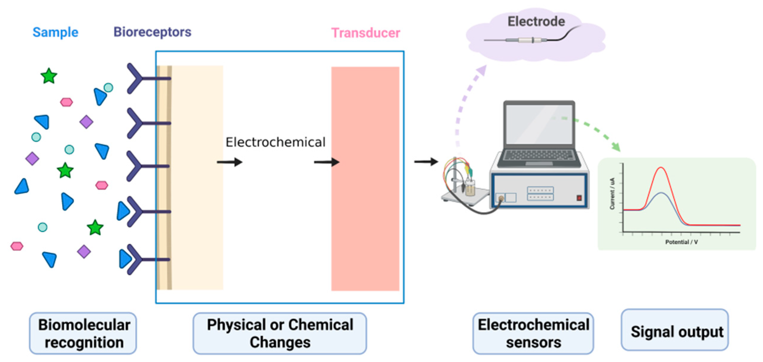
Bipolar Electrode Arrays For Chemical Imaging And Multiplexed Sensing Acs Omega

Hall Effect Sensor Directions
Biosensors Free Full Text Electrochemical Signal Amplification Strategies And Their Use In Olfactory And Taste Evaluation Html

Low Cost Hall Effect Sensor Hall Effect Sensor Electrical Circuit Diagram
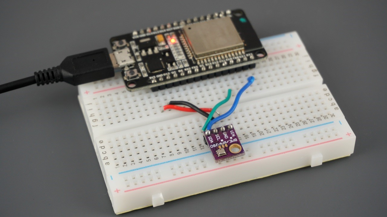
Esp32 With Bme280 Using Arduino Ide Pressure Temperature Humidity Random Nerd Tutorials

Pin On Programming

Introduction Hall Effect Switches Sensors Circuits Tutorial Hall Effect Sensor Circuit

Schematic Hall Effect Sensor Toggle Switch